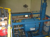
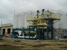
Ethanol Dryer
Description:The Ethanol Dryer utilizes low watt density heaters inserted in non-removable stainless steel thermowells spaced throughout the desiccant bed. This design distributes the reactivation heat uniformly over the entire cross sectional area, obtaining complete and thorough reactivation of the desiccant.
SF6 Gas Re-Circulation and Contitioning System
Description: The blower pulls gas from the process and directs it to the heat exchanger where it is cooled. The cool gas is then directed to Molecular Sieve Internal Heat Reactivated adsorber and finally through a filter and back to the process.


The heat exchanger use cooling water to reduce the elevated gas temperature from the process to about 70°F prior to entering the adsorber. The adsorber is used to remove any trace amounts of moisture to pressure dew point of less than minus 70°F
Solvent Dryer
Description: Wet liquid enters the equipment and is dried as it flows through the desiccant bed and discharges the equipment. Adsorbents can be Molecular Sieves or Ion Exchange Resins. The dryer is a closed loop design and can be modified to meet a variety of applications. The unit shown here is drying a number of different solvents ranging from IPA, Ethanol, Acetone and Thinners.
Regeneration is accomplished as follows:
Drain (Solvent Transfer)
Reactivation of the spent tower begins when the transfer valve, nitrogen inlet valve and vent valve are opened allowing the liquid in the drying tower to be displaced out of the tower by high pressurized nitrogen to the reactivated vessel. Transfer is controlled via level switches. The tower pressure is then equalized with the reactivation skid pressure. The exiting gas from the tower being filled is vented to a vapor recovery system.

Heating
Bed reactivation is accomplished by re-circulating the trapped volume of nitrogen through the bed by means of a blower, heater, and condenser reactivation loop. As the gas is heated and directed to the bed, it liberates the water, which is then condensed and separated. Once the bed reaches the proper reactivation temperature, the heating is de-activated.

Cooling
The nitrogen gas continues to circulate after the heating is stopped until the proper cooling temperature is reached.


